
Section under development
This winder originally had a Markham steam operated brake-engine acting on a Burns type undershod rim brakes - deadweight applied, steam released.
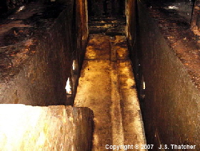
The vertical brake engine was located on the engine-house floor a few feet to the rear of the drum, with suspended dead weights hung below it in the drum pit. The brake-engine operating rod was connected to a bell-crank lever mounted on an arched brick pillar straddling the drum-pit closer to the drum. The pivoted brake shoes were mounted on long levers which had a fulcrum just beyond the axis of the drum shaft, the other end being connected to a 7 in. diameter cross-shaft keyed to the bell-crank lever. The brake lever front fulcrums were mounted on 30in wide brick foundation walls running below the drum.
The foundations and bed-bolts for this brake can still be seen in the drum-pit. The support girders and bolt holes for the brake-engine can also be seen beneath the engine-house floor near the support pillar for the brake operating lever fulcrum.
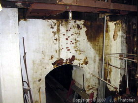
South winder 1922 brake operating lever foundation pillar.
South winder 1922 brake-lever foundations.
The brake-engine was steam operated with a 10. diameter cylinder with an 18 in. stroke. A hydraulic cataract cylinder was interposed to avoid harsh operation and to lock the brake in position. The steam valve was operated by a floating lever arrangement with linkages to the brake bell-crank, the drivers hand lever and the operating rod from the Thornwill and Warham overwind device. The bell-crank and drivers linkages were arranged to apply the brake in accordance with the position of the drivers handle whilst the overwind linkage applied the full braking power immediately
As part of the major upgrade in the early 1950s, the Burns brake was replaced by a Markham suspended-post brake. The V shaped brake paths were retained, along with the original brake-engine and weights, although a larger diameter steam cylinder was fitted.
To accommodate the base plates for the front suspension posts, the brake foundations had to be built up above the original access steps at that front end and replacement steps were constructed alongside the rear.
In the mid 1960s Robey pillar brakes were installed - spring applied, hydraulic released. This brake, its hydraulic power-pack and sections of the pipework are still in-situ.
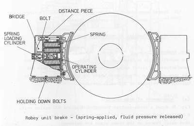
Schematic diagram of the Robey Crompton unit brake.
The V shaped brake paths were replaced with flat profile ones which were trued up in-situ by fixing a cutting tool onto a strong bracket mounted on the brake foundation platforms, and then, using the drum as a giant lathe, the brake path was machined concentric. The bracket which held the cutting tool can still be seen on the right hand foundation.
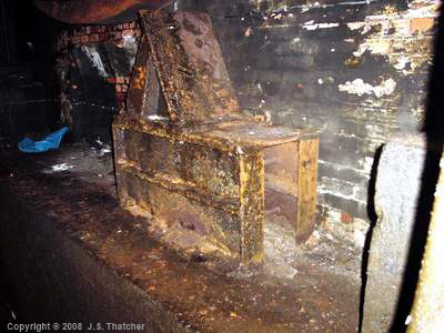
South winder 1966 brake-path machining bracket.
References
- Markham & Co. Ltd. engineering drawing # 20310, 20311 (1921)
- Markham & Co. Ltd. engineering drawing # 26562 (1950)
- Markham & Co. Ltd. engineering drawing # ......... (1965)
Copyright © 2005 - 2020 J S. Thatcher
Page updated on:
02 Aug, 2020
at
09:33:44 PM
In case of problems contact: