
Section under development
|
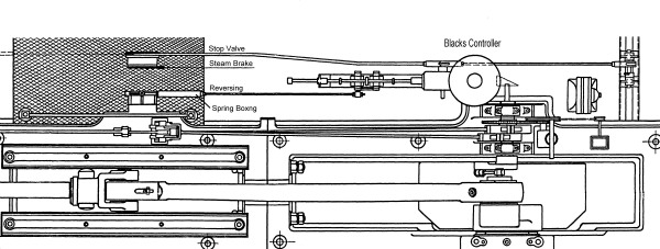
In 1923 a Barclay’s overwind protector was in operation on this winder. In the early 1930s, a Blacks Profile controller located adjacent to the LH main bearing appears on the drawings for the replacement brakes installed by Lilleshall Co. but a Thornwill & Wareham device was fitted instead. In 1950 a Thornwill & Wareham overwind protector and Kings slow-banker similar to those fitted to the South winder were in use. By 1973 these had been replaced by a Black’s Torque automatic protection device. |
|||
 |
|||
North winder proposed Blacks Profile controller layout circa 1930 (FoPP/JST)
|
A spring operated de-gabbing or uncoupling device is located in the linkage behind the drivers chair and shut off the steam valve automatically in an emergency. This was normally held off by hydraulic pressure which was only released during activation of the overspeed / overwind protection device. It’s not clear when this was installed, but it would have been after the Markham brake was fitted since it needed hydraulic pressure. It would also have needed the Blacks Torque controller for the activation of its electrically controlled release valve. This system replaced the mechanical linkage operated by the Thornwill and Warham device fitted in 1931. |
|||
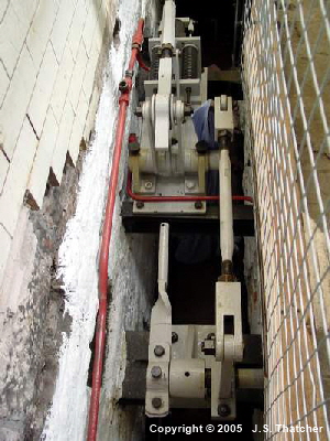
North winder steam valve over-ride linkage (click on the components to show their function)
The steam valve is a double-beat type and the drivers throttle lever operated this unassisted. It is located below floor level at the rear of the engine. Between the valve and the inlets there are two hydraulically operated dump-valves. The dump-valves allowed steam pressure to be instantly released from the engine in case of an emergency stop. They were a late addition, possibly resulting from the Markham disaster.
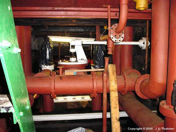
North winder steam throttle valve and emergency dump valves.(click on the components to show their function)
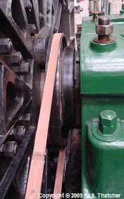
Both the Worsley Mesnes and the Lilleshall winders operated with the valve cut-off mechanism actuated by a belt driven governor. On the former winder the drive pulley was on the outside of the RH trailing crank bearing whilst on the latter it was located between the drum and the RH valve rocker eccentric.
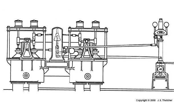
North winder governor and cut-off layout circa 1930 (FoPP/JST)
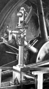
Governor on original winder circa 1904. (FoPP/JST)
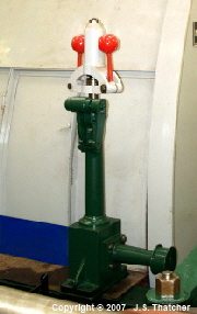
Present North winder governor
North winder governor drive pulley
The governor is a modified weighted pendulum type designed by Hartnell in the mid 19th century. A vertical shaft inside the column is rotated by the pulley shaft in the base via a bevel pinion arrangement. The top of the shaft is attached to a cylindrical casing with a horizontal D shaped frame at its base. The tips of the frame carry the pivots for two bell-crank levers carrying the governor balls. The inner arms of the bell-cranks press on a strong spiral spring located inside the cylindrical casing via a metal sleeve surrounding the vertical shaft. The sleeve itself extends below the D frame where it ends in a double collar. A forked lever forming one end of another bell-crank lever fits inside the collar whilst the other end is connected via to a link rod to the valve cut-off mechanism.
As the drum turns, the governor shaft rotates and with it, the two balls. These are thrown outwards and compress the spring whilst at the same time moving the cut-off link rod. The amount of compression of the spring is determined by the rotational speed of the balls, as the speed increases, the balls are thrown further out and the cut-off is advanced.
The cut-off link rod (and the cut-off mechanism itself) was removed sometime in the 1970s after coal winding had ceased at the North pit.
References
- Journal Notts Min. Students (1924)
- Markahm’s engineering drawing # (1924)
- Lilleshall Co. Ltd. engineering drawing # (1930)
- Colliery Engineering (1950)
- NCB documentation (1973)
- Audel’s Engineers and Mechanics Guide 1 (1921)
Copyright © 2005 - 2020 J S. Thatcher
Page updated on:
27 Jul, 2020
at
07:58:57 PM
In case of problems contact: