Technical | Shafts | Pit bottoms > South pit
Section under development
The early South shaft terminated at the Top Hard seam level. When the shaft was deepened in 1920 it was extended to the Black Shale seam but was only worked down to the Deep Hard level and, strictly speaking, the shaft foot was an inset.
The shaft-side roadway width was about the same as the shaft diameter since in the original layout, the tubs arrived and left the shaft side via different roadways, unlike some collieries where the pit bottom was widened out to allow tubs to pass alongside of the shaft.
Post 1922, this shaft operated a three deck simultaneous loading system and the pit-bottom roadway heights reflected that. During the 1950s modernisation the pit bottom was substantially altered with a single decking level constructed a few feet above the original bottom-deck level and the full & empty sides were reversed. The pit bottom brickwork, however, remained largely unchanged.
The layout of the mine-car circuit now required the empty mine-cars to be returned to the full side roadway, and in order to achieve this a brick-lined snicket was driven about 6ft / 2m to the left hand side of the shaft. The empty side was graded to allow the unloaded mine-cars to run past the snicket entry to an automatic pneumatic reversal ram which propelled them back via switch points into the snicket onto a Lofco chain creeper which carried them along the gradually rising track until they could gravitate toward the loading point.

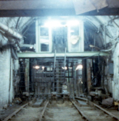
Looking towards the South pit shaft foot - full-side Deep Hard seam circa 1984, after closure. (FoPP/JST)
In the photograph above, taken from the full side, something of the original height of the pit bottom can be appreciated. The onsetters cabin sits above the mine-car tracks with its access ladder between them. The cabin was over 6ft high and over 6ft above ground level.
The full mine-cars gravitating to the shaft side had their momentum arrested by a pair of pneumatic clamps which gripped special bars along the sides of the mine-car. These clamps can just be discerned on either side of the rails in front of the ladder. The loading rams were located underneath the steel cover plates between the tracks alongside the clamps.
Keps were not used at the pit bottom since the stretch of the winding ropes due to the load led to cage positioning variations. Instead, the mine-car tracks ended with a short hinged plate which could be lowered onto the cage hoop. These plates can just be discerned in the elevated position in front of the shaft gates. The cage would sink perhaps 12 in. as the full mine-car was pushed on, but this acted in favour of the loading. Sufficient momentum was given to the empty mine-car to ensure that it overcame the increasingly adverse gradient as it left the cage.
The shaft gates above the drop-plates hung from rollers and ran on hinged bars which could be tilted by small pneumatic rams in order to open the gates.
On the left hand side of the tunnel are the methane drainage discharge pipes from the Piper seam, whilst on the right hand side several shaft cables can be seen.
TOP
Copyright © 2005 - 2020 J.S. Thatcher
Page updated on:
27 Jul, 2020
at
07:47:21 PM
In case of problems contact: