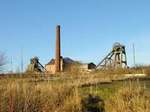
Section under development
North pit shaft guides
When the North shaft was sunk it was fitted up with wooden guides for the cages. Working three shifts of eight hours for seven days a week this took three months to complete and cost £1,722 (1877 prices) excluding the cost of fixing the wall-boxes which carried the oak cross-stays. Initially, Oregon pine was tried for the guide rails but it was found to be unsatisfactory and was replaced by pitch-pine.
1877-1950
- type wooden rails
- number 4 per cage (2 each side)
- material Oregon-pine then pitch-pine
- size 4.75in x 4.25in
- cross-stays (byatts/buntons)
- number 1 central, 2 outer
- material oak
- size
- central 9in x 8in x 16.5ft
- outer 9in x 6in x 14ft
- seperation 10ft
- fixing
- a) brackets cast on tubbing
- b) cast-iron boxes in shaft wall
1950-1983
- type bull nose rails
- number 2 per cage on outside
- material steel
- size ??
- length 36ft
- cross-stays (byatts/buntons)
- number 1 each side of shaft
- material ? double steel channel
- size
- outer ? 9in x 6in x 14ft
- seperation ? 10ft
- fixing
- a) brackets cast on tubbing
- b) cast-iron boxes in shaft brickwork
South pit shaft guides
In 1888 the South shaft was upgraded to allow coal winding. Twin-deck cages with two 1⅛in diameter guide ropes on each side were installed. When the new headstock was installed and the South shaft infrastructure upgraded in 1900 the guide ropes were re-arranged to give three 1½in diameter guide ropes on the outside of each cage and two 2in diameter rubbing ropes between the cages, each of which were fitted with oak rubbing boards. Due to the wetness of the shaft the lifetime of the ropes was only about 5 years rather than the 12 - 15 years normally obtained in a dry shaft.
The ropes were suspended from the headframe by clamping to short stub ropes or bars. It had been found that most guide rope fatigue occurred near to the suspension points and so the ropes were shortened at regular intervals by pulling a few feet up through the suspension clamps. The excess rope was left dangling until the rope itself was renewed.
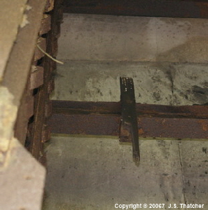
At the top of the shaft, the cages engaged with short wooden receiver guides which positioned it in line with the tub-rails. A fragment of one of these guides is still in place in the South headframe.
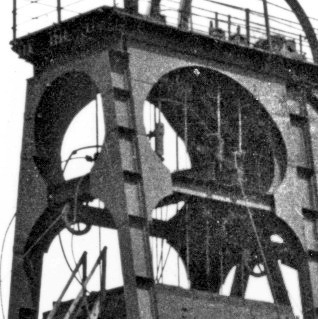
Guide rope suspension system on the South pit headstock. 1900 - 1920 (FoPP/JST)
Remains of a wooden cage decking -guide in the South pit headstock. 1900 - 19??
When the South shaft was deepened in 1922 the distance was considered too great for guide ropes and these were replaced with steel rails fastened to buntons across the center of the shaft. The buntons consisted of a pair of steel channel irons mounted horizontally back-to-back and were inserted into holes made in the shaft brickwork. What was done in the section which had the tubbing is uncertain, but would probably involve support brackets bolted to the tubbing itself. Long steel plates were bolted to the sides of the buntons and the rails were secured to these by steel clamping bars.
The cages were attached to the guide rails by steel slippers at each corner. Unlike the photos below which were taken during salvage operations after closure, the rails and slippers were kept well greased.
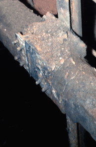
South pit guide-rail attachment arrangement. (FoPP/JST)
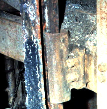
South pit guide-rail with cage slipper. (FoPP/JST)
- 1879-1888
- unknown
- 1888-1900
- type rope
- number 4 per cage
- material iron
- size 1½in dia
- hangers ??
- tension cheese weights in sump
- 1900-1919
- type rope
- number
- 3 on outer side of cage
- 2 central rubbing ropes
- material iron ? steel
- size
- 1½in dia cage
- 2in dia rubbing
- hangers clamped to stub rod?rope
- tension cheese weights in sump
1922-1990
- type bull nose rails
- number 2 per cage on inside
- material steel
- length 36ft
- size 5in base : 4in x 2in nose
- type twin channel-iron
- number 1 central
- material steel
- size 2 @ 8in x 4in
- length
- 16ft brickwork
- 14.5ft tubbing
- weight approx ½ ton
- separation ? 10ft
- fixing
- fixed in wall
- bracket on tubbing
Sources
Mr Allen Hill’s personal records (Shaftsman)
|
Copyright © 2005 - 2020 J.S. Thatcher |
|||||
|
25 Aug, 2020 |
|||||
|
Page updated on: |
|||||
at
11:36:55 AM
In case of problems contact: