Section under development
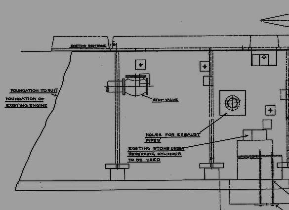
North winder 1904 Lilleshall foundation plan - rear half (FoPP / JST)
The front edge of the old winder bed-frame was used as the datum point for the dimensions, with the centre of the first bed-bolt located 8in away.
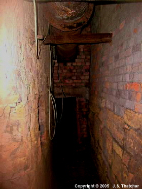
North winder LH side foundation pit.
An early engine bed-bolt pocket is located in front of the brick pillar and another which still contains the bed-bolt is just below the view-point
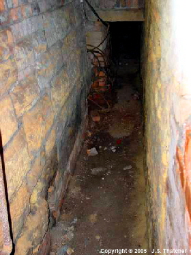
North winder RH side foundation pit.
Bed-bolt pockets from the early engine are located in the lower LH corner and in front of the brick pillar.
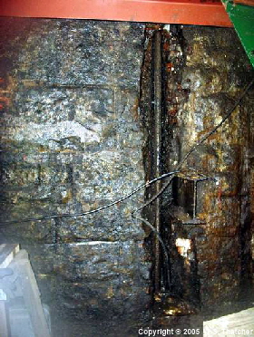
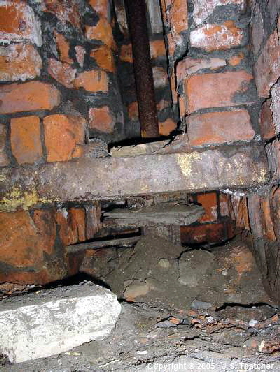
North winder RH side cylinder front-inner bed-bolt
North winder RH side outer front bed-bolt
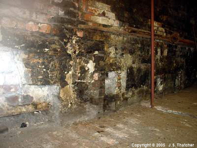
North winder drum pit RH rear side.
4 bed-bolt pockets from the early engine are located here.
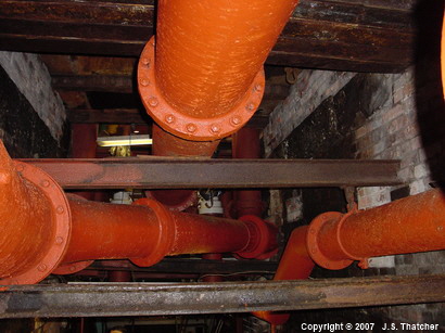
Original North winder bed-stones. The oil stains are from the drum bearings.
|
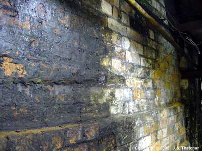
In the drum-pit at the rear of the existing engine there are a number of old bed-stones in the piers just below the engine-house floor. The top of these is believed to be the original floor-level of the engine-house. There are the remains of a line of support timbers bolted to the bed-stones in the RH and LH foundation pits which would have supported the wooden flooring over the pits. The pit-top outside had been raised by 15in when the new headframe was installed in 1901. There are 5 courses of bricks above the bed-stones suggesting that when the winder was replaced in 1904 the internal floor level was raised to bring it just above outside ground level. On the wall of the LH pier in the drum pit there is an arcuate groove in the brickwork which coincides with the location of the original winding drum. It is believed that this was caused when the drum shaft failed. It is covered by oil staining which suggests that the engine continued in use for some time afterwards, following the fitting of a new drum-shaft. Measurement of the groove gives a chord length of about 44 inch with a height of about 2 inch. These values yield a radius of 122 inches, consistent with the 20 ft. reported diameter of the drum. The lowest point of the groove is about 90 inch below the top of the large bed-stones indicating that the centre of the drum shaft was 30 inch above floor level. |
|||
 |
|||
Groove from early drum rim on LH wall of North winder drum pit
The groove can be seen starting 2 courses of bricks up in the lower LH corner and fading out 6 courses higher on the RH side
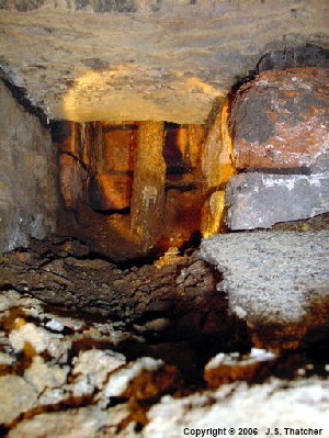
bed-bolt from original winder still in-situ
TOP
Copyright © 2005 - 2020 J S. Thatcher
Page updated on:
27 Jul, 2020
at
07:58:57 PM
In case of problems contact:
