Section under development
The usual purpose of expansion gear was to cut off the steam to the cylinder at an early point so as to allow it to continue to do work by expanding, thus resulting in a much more economical operation.
In the case of a winding engine, however, it served a completely different purpose, which was to automatically reduce the amount of steam used after the heavy demand during the acceleration of the winding drum and its load up to running speed had ceased.
Both the original Worsley Mesnes engine and the Lilleshall engine utilised a Mellings Patent rising-wedge cut-off device. In the early 1970s, when fast coal winding at the North shaft had ceased, the governor operating link was disconnected and the engine was run with no cut-off. Unfortunately the trip operating mechanism itself was also removed but luckily the Lilleshall drawings for it still exist as does a photo showing the set-up in the 1960s.

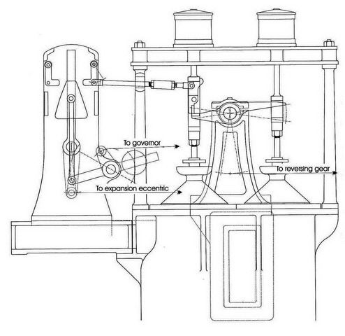
Lilleshall drawing (1931) showing expansion mechanism arrangement. (FoPP/JST)
The mechanism consisted of a wedge-shaped block which could slide up and down the upper section of a pivoted bar inside the central frame. The lower end of the bar was connected to a “rocker” shaft operated by an eccentric on the drum-shaft. The wedge was lifted by the operation of the governor, and as it did so, it came closer to the ends of the push-rods connected to the trip catches in the valve lifting mechanism. As the wedge oscillated to the right and left, it pushed the rods and tripped the catches, thus disconnecting the valve spindles from the tappets and allowing the valve to close early. The greater the speed, the higher the wedges were lifted and the earlier the trip mechanism operated.

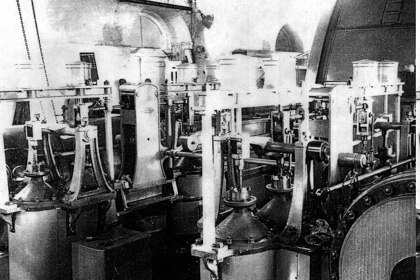
In this grainy photo from the 1960s, the operating mechanism and governor linkage is still in place. One governor ball can just be seen on the upper RH edge, the rest being hidden by a funnel shaped cover. The RH valve-rod can be seen but the rocker-rod is out of sight behind the cylinder.


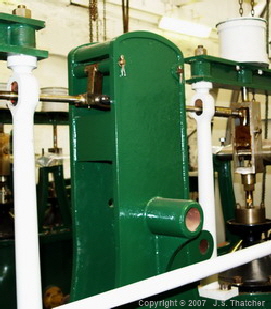
RH side operating mechanism housing - minus the rising wedge mechanism. The bush on the side carried the shaft from the rocker lever
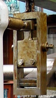
Inlet valve trip plate and tappet.
Copyright © 2005 - 2020 J.S. Thatcher
Page updated on:
05 Aug, 2020
at
01:22:08 PM
In case of problems contact: