
Section under development
The 1874 Worsley Mesnes winder had foot and steam operated brakes. The brake itself was a band type enclosing the full brake path. The operating fulcrum and linkage were below floor level at the rear of the drum. The location of the steam cylinder was probably below floor level too.
The foot brake would have been used at slow speeds and the steam brake when the cage was stopped or in case of emergency.
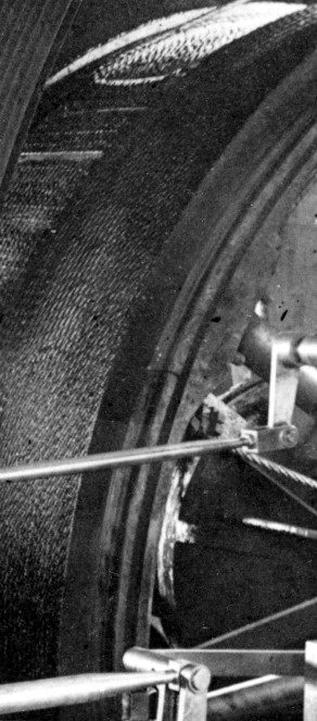
North winder RH brake-band circa 1903 (FoPP/JST).
The 1905 Lilleshall winder had a steam-operated brake (and possibly a foot brake). The steam cylinder was below floor level at the rear of the drum. The cylinder was mounted an a 2ft. 8in. high masonry plinth and secured by four 11/4in. bolts fastened to a cast iron foundation plate buried 2ft. 6in. below the floor of the drum pit. This could possibly have been the steam brake from the earlier Worsley Mesnes engine. It operated a band-brake which, from the Markham drawings for a replacement in 1924, would appear to have been have been a full band.
In 1924, the steam brake was replaced by Markhams with a new brake-engine and a 5700 lb dead-weight (deadweight applied, steam released). This operated a two part band-brake with a steam operated brake-engine located on the engine-house floor where the present day stairway to the drum-pit is. (The foot brake facility appears to have been discontinued at an earlier stage).
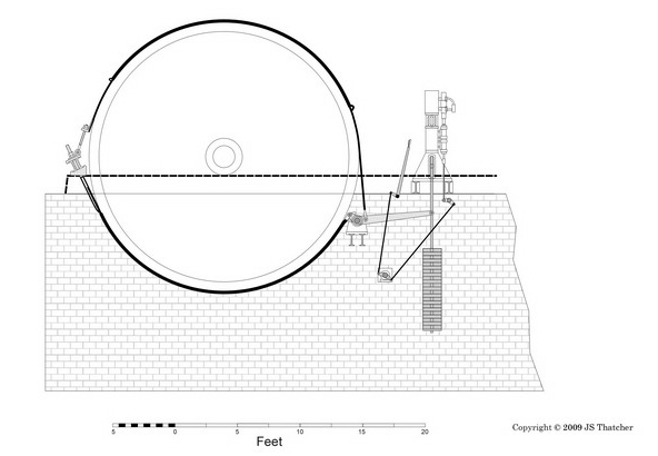
Markham’s 1924 band-brake and brake engine arrangement
The brake bands were attached to the bedframe by adjusting bolts mounted on two RSJ girders which ran across the front of the drum. These RJSs were secured to the ends of the RH and LH bedframe by angle brackets, one of which is still in-situ.
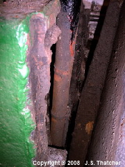
In order to accommodate the tensioning screws, the cross-member of the front bed-frame appearing on the original Lilleshall drawings would have had to have been removed. If this was the case, the loss of this main bracing component on the section which took the full stresses of the cranks would inevitably lead to structural failure and could account for the subsequent problems with bedplate fractures.
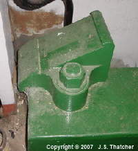
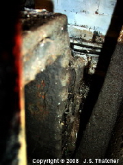
brake-band front girder bracket
LH front bedframe under the bracket showing the broken edges of the casting where the cross-member was removed.
The band brake was eventually replaced by Lilleshalls in 1931 with a Blacks Spring post-brake (deadweight/spring applied, steam released), and this, together with the Markham brake-engine remained in use until the mid 1960s. It is rather surprising that it took so long to fit this superior type of brake since the Lilleshall Co. had taken over the rights to it in the early 1900s.
In this type of brake the service and emergency braking operations were performed by separate mechanisms. Under normal service braking the application was controlled by the dead-weight and brake-engine. These could be relatively slow to operate in an emergency, however, whilst the shock of application could result in damage to the drum, rope and brake linkages. In an emergency such as an overwind, the Black’s brake was applied by releasing a small toggle which normally held the springs under compression. These springs acted on the rod connecting the brake shoes, bringing them very quickly into contact with the drum. Subsequent activation of the service brake mechanism allowed the toggle to be reset.
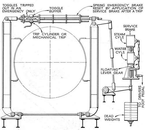
Basic arrangement of Blacks Spring Brake system
The fitting of this brake required the replacement of the brake rim on the drum, plus modifications to the LH expansion gear rocker-shaft in order to clear the brake post.
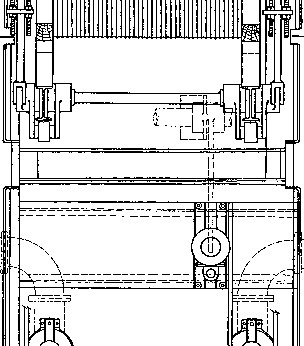
Plan view of the North winder brake-engine layout circa 1931 (FoPP/JST)
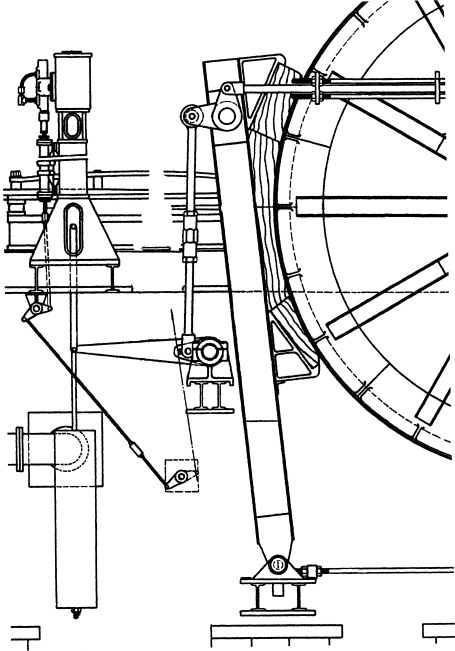
Side elevation of the North winder brake-engine layout circa 1931 (FoPP/JST)
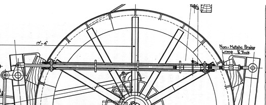
North winder Black’s brake spring-nest rods and emergency release toggle circa 1931 (FoPP/JST)
In the 1960s a spring applied / hydraulic released caliper brake, newly developed by Markhams, was installed. This brake and its control unit are still in-situ although not operational at present.
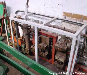
North winder brake hydraulic control unit.
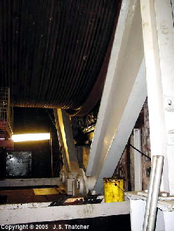
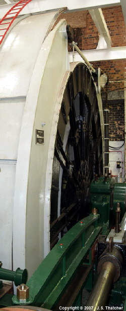
North winder RH side brake calipers
North winder RH side brake caliper lower pivots
References
- Lilleshall Co. Ltd. engineering drawing # 17996 (1904)
- Markahm’s engineering drawing # 18082, 21060 (1924)
- Lilleshall Co. Ltd. engineering drawing # (1930)
- Markahm’s engineering drawing # (1965)
Copyright © 2005 - 2020 J S. Thatcher
Page updated on:
28 Jul, 2020
at
06:08:54 PM
In case of problems contact: